


Motor protector
Contact us
Fax:0577-59921167
Chief:Mr.chen
Address:Geyao Building, the Junction of Shanhai Road&Haixia Road, Industrial District, Cangnan County, Zhejiang Province
Zip:325800
E-mail:cngydz@163.com
Set design, development, production, production and sales services as one of the diversified enterprises, the original high-end motor protector, successful research and development of intelligent integrated motor protector, motor protector, microcomputer protector, power meters, switchgear intelligent control device, service robot and other products.

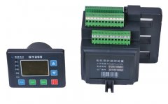
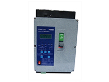
GY205 motor protection device
- GY205 motor protection device 1 、 Product Introduction The intelligent, networked, digital LCD wide screen display motor protection device which our company developed is according to the IEC international standards.At first , It combines
- support hotline:13732088722
-

-
Product Details
GY205 motor protection device

1、Product Introduction
The intelligent, networked, digital LCD wide screen display motor protection device which our company developed is according to the IEC international standards.At first , It combines the advanced network communication technology with the distributed intelligent technology in the MCC control center.And it integrates motor intelligent protection, integrated electrical quantity measurement and remote on-off operation control, operation state monitoring, fault recording and network communication.At last , it can view the measured data, DI / DO status, alarm information, fault information management, motor information management, parameter setting, motor start and stop, etc., and can satisfy the multi-party starting mode .It can be directly installed and used in low-voltage control terminal MCC cabinets and 1 / 4 units and above various drawer cabinets. on.Its measure protection avoided the productive accidents caused by the motor fault like overload , locked-rotor , overvoltage , undervoltage, underload, open-phase, electrical grounding earth etc. and ensured the equipments’ normal function and sfety .
Its fieldbus RS5485 interfaces support various protocols which can be used in many microcomputer industrial control configuration software to complete the network communication management,on the other hand, it can also connect with the DCS system by the way of 4-20 Ma variable signal output, then transmit and output the operating parameters of the motor to form a distributed integrated electric power monitoring system.Standard configuration, perfect function, these greatly simplifies the maintenance of the motor circuit in the traditional sense and reduce the equipment maintenance cost,so it provides scientific and effective field level protection, measurement and control unit for industrial production process control.

l Field level protection, measurement and control unit
l Integrated all-round motor intelligence, digitalized protection and network communication
l Apply the advanced network communication and distributed intelligent technology in the MCC panel.
l Continuous monitoring, flexible control
2、Model¤t specification
|
Model |
Power range |
Current range |
Remark |
|
06 |
0.1-2.5kw |
0.2-6A |
Wring through the protection device CT hole directly |
|
10 |
1.5-4.5kw |
3-10A |
|
|
30 |
3-11kw |
5-30A |
|
|
50 |
5-20kw |
10-50A |
|
|
100 |
11-45kw |
20-100A |
|
|
150 |
20-75kw |
40-150A |
|
|
200 |
20-90kw |
40-200A |
Provide 200/5,Wring through the protection device CT hole second time |
|
300 |
30-110kw |
60-300A |
Provide 300/5,Wring through the protection device CT hole second time |
|
400 |
45-200kw |
80-400A |
Provide 400/5,Wring through the protection device CT hole second time |
|
500 |
50-250kw |
100-500A |
Provide 500/5,Wring through the protection device CT hole second time |
|
600 |
60-300kw |
120-600A |
Provide 600/5,Wring through the protection device CT hole second time |
|
800 |
100-400kw |
160-800A |
Provide 800/5,Wring through the protection device CT hole second time |
3、Technical Parameter
|
Routine description |
Protection function |
|||
|
Working Power |
AC85-265V,AV220V,50Hz |
Overload protection |
√ |
|
|
Circuit voltage |
AC380/660V(〉660Vremark the change) |
Short protection |
√ |
|
|
control relay output capacity |
5A,250VAC |
Locked-rotor protection |
√ |
|
|
Programmable relay output capacity |
5A,250VAC |
earth(leakage)protection |
√ |
|
|
Power consumption |
〈5W |
Open-phase protection |
√ |
|
|
Fieldbus |
1、MODBUS-RTU protocol,baud rate 9600-19200bps 2、PRODIBUS-DP protocol,baud rate 9600-6000000bps |
underload protection |
√ |
|
|
Overvoltage protection |
√ |
|||
|
工作环境 |
Working temperature -30~+75℃ Storage condition -40~+85℃ Relative humidity5%~95% height≤2500m |
Undervoltage protection |
√ |
|
|
Time-out protection |
√ |
|||
|
overheat protection |
√ |
|||
|
Anti-interference start |
√ |
|||
|
Pollution grade |
Ⅱ |
Control fuction |
||
|
Protection grade |
IP20 |
Direct start |
√ |
|
|
Installation way |
Standard 35mm leadrail、screw fixed directly |
Direct bypass start |
√ |
|
|
Application |
three - phase asynchronous motor, frequency control , increased safety motor、feeder |
Forward and reverse start |
√ |
|
|
Digital input |
Programmable Digital input internal power supply, Photoelectric isolation 12 channels |
Star-triangle start |
√ |
|
|
Control relay output |
6channels |
Automatic step-ddown start |
√ |
|
|
Analog output |
DC4-20mA,internal power supply 24V DC, conversion accuracy:0.5%FS |
Soft start |
√ |
|
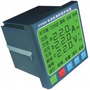
4、Structure&size
Current tansformer

Main body:
Consists of electronic components tripping protection film, current transformer.Fixed on standard lead rail or Directly installed by screws.
Operation panel:
Installed in the door or the drawer door. Use the control button and LCD on the opration panel to complete the control,monitor and paramiter setting.
Connect:
Operation panel is connected to main body by RJ11 interface
Attention! The connecting wire should not be a live wire.The operation panel LCD will show communication fault if the connecting is failed
Installation size(Unit:mm)


5、Terminals interface
Five I/O rows of terminals, I/O terminal boards are installed on the main body(Just as the drawing below)。

5.1Terminals definition
|
Terminal rows |
Terminal NO. |
definition |
remark |
|
X1 |
X1:1…13 |
Digital I/O input |
Maximum terminal diameter is 1.5mm2 |
|
X1:14 |
DC24V output |
||
|
X1:15,16 |
Thermistor input(PTC) |
||
|
X2 |
X2:1…6 |
Operation panel interface |
Standard RJ11interface |
|
X3 |
X3:1…4 |
hold external CT input |
Maximum terminal diameter is 2.5mm2 |
|
X4 |
X4:1…4 |
three-phase voltage measurement input |
|
|
X4:5,6 |
Zero-sequence CT current input |
||
|
X4:7 |
Earth terminal |
||
|
X4:8,9 |
4-20mA analog output |
||
|
X4:9…11 |
RS485communication interface |
shielded twisted pair |
|
|
X5 |
X5:1…5 |
programmable relay output |
Maximum terminal diameter is 2.5mm2 |
|
X5:7…10 |
Control relay output |
||
|
X5:11,12 |
220V AC power input |
5.1.1 Power input terminals +
|
Terminal No. |
Name |
Description |
|
X5:11 |
L(+) |
Power input AC 220V live wire |
|
X5:12 |
N(-) |
Power input AC 220V null line |
5.1.2 Digital input terminals +
Provide 13 digital input terminals, select internal DC24V power supply.The device tests the input terminals and judges the signal input. Digital input terminals include 3 programmable terminals which can be definited according to the users’ requirement.
|
Terminal No. |
Name |
Description |
|
X1:1 |
Start 1 |
Start button1input |
|
X1:2 |
Start 2 |
Start button2input |
|
X1:3 |
Stop |
Stop button input |
|
X1:4 |
Reset |
Fault reset button input |
|
X1:5 |
Heat capacity |
Heat capacityclear buttoninput |
|
X1:6 |
Feedback 1 |
contactor1rivet feed back input |
|
X1:7 |
Feedback 2 |
Contactor2rivet feed back input |
|
X1:8 |
feedback 3 |
Contactor3rivet feed back input |
|
X1:9 |
Programmable input 1 |
programmable digital input1 |
|
X1:10 |
Programmable input 2 |
programmable digital input 2 |
|
X1:11 |
Programmable input 3 |
programmable digital input 3 |
|
X1:12 |
Emergency stop |
Emergency stopbutton input |
|
X1:13 |
External switch position |
Switch condition |
|
X1:14 |
DC24V |
DC24V output |
5.1.3 PTC(thermistor)input terminals +
Monitor the motor winding temperature by PTC sensor.
|
Terminal No. |
Name |
Description |
|
X1:15 |
PTC_+ |
PTC inputA |
|
X1:16 |
PTC_- |
PTC inputB |
5.1.4 Communication fieldbus interface terminals +
ProvideRS485 communication interface. Communication medium requires to use shielded twisted pair.
|
Terminal No. |
Name |
Description |
|
X4:12 |
SHIELD |
RS485 shield |
|
X4:10 |
TA |
RS485 A+ |
|
X4:11 |
TB |
RS485 B- |
5.1.5 Three –phase voltage measurement input terminals +
Measure the three-phase voltage continuously to complete the protections related to voltage.
|
Terminal No. |
Name |
Description |
|
X4:1 |
Ua |
A phase voltage input |
|
X4:2 |
Ub |
B phase voltage input |
|
X4:3 |
Uc |
C phase voltage input |
|
X4:4 |
N |
Neutral point input |
5.1.6 Leakage zero-sequence transformerinput terminals(RCT) +
Zero-sequence current transformer(LJ-5A zero-sequence transformer)monitors the earth fault current.Use apertureΦ48 Zero-sequence current transformer if below 150A, Use apertureΦ75 Zero-sequence current transformer if above 150A.
|
Terminal No. |
Name |
Description |
|
X4:5 |
K1 |
Leakage CT output A |
|
X4:6 |
K2 |
Leakage CT output B |
5.1.7 4~20mA current output terminals +
Output analog current 4-20Ma, Direct access to industrial secondary instruments or DCS systems for centralized control. 4mA is OA current, 20mA is specification current, Users can set the setting current according the need。
|
Terminal No. |
Name |
Description |
|
X4:9 |
+ |
4-20mA output+ |
|
X4:8 |
- |
4-20mA output- |
5.1.8 Three-phase main current measurement terminals +
Measures the motor’s three-phase current continuously.The wire can run through CT hole from each side, but the three wire should run through the CT hole from the same side.The device over 150A should not run through the CT hole directly and need the other CT(outputis 5A, accuracy must be above class 0.5) to assist the measurement.
Note:For the single phase motor circuit, the current measurement is done by the CT’s A phase.The aperture is 23mm.
5.1.9 Programmable control relay output terminals +
Provide two groups of assistant programmable relays output(apply in the every scenes discribed in the 6.3.3)
|
Terminal No. |
Name |
Description |
|
X5:1 |
programmable output control relay 1_A |
programmable output control relay 1(INO+INC) |
|
X5:2 |
programmable output control relay 1_B |
|
|
X5:3 |
programmable output control relay 1_C |
|
|
X5:4 |
programmable output control relay 2_A |
programmable output control relay 2(INO) |
|
X5:5 |
programmable output control relay 2_B |
5.1.10 Control relay output terminals +
Allows many motor start modes, using the microprocessor to control the internal relay to do the external intermediate relay or contactor control.
|
Terminal No. |
Name |
Description |
|
X5:9 |
Control relay 1 |
Control relay output 1 |
|
X5:8 |
Control relay 2 |
Control relay output 2 |
|
X5:7 |
Control relay 3 |
Control relay output 3 |
|
X5:10 |
Common terminals |
Relay controls the current input |
5.1.11 Earthing protection terminals +
The protective earthing of this device eliminates the instantaneous interference and the possible damage caused by the surge and improves the reliability of the device. The earthing protection terminal must be strictly connected to the protective site of the system to ensure the reliability of earthing。
|
Terminal No. |
Name |
Description |
|
X4:7 |
Earth terminals |
Safety protection earth |
5.2 Typical application diagram +

Note:1)When the power is not on,control1, control2, control3 and programmable1,2 are always opening.
2)When the power is on,control1、control2、control’s conditon is decided by the signal they received.
3)When the power is on,programmable relayoutput confition is decided by system setting.
6.3.3 Communication +
Communicates with upper computor by the RS485 interface.Fieldbus interface supports the parameters setting,control and monitor.Protocol complies with Modbus-RTU、PROIFBUS-DP standard.Use the RS485 fieldbus interface to do the physical connection.The upper computor or PLC equipment is the main station in general
6.3.4 Fault query function +
Can record the three latest fault information,includes the motor fault reason and tripping action value.
6.3.5 Programmable interface +
provides three programmable input terminals and two programmable output relay, all conditions below can user-defined in the upper computor or operation panel
|
1、Start delay closing:The programmable output relay’s contact point will delay closing after the motor is started. |
|
Set:Select start delay closing in the setting menu 18-1 page "digital output 1" or 20-1 page "digital output 2" on the operation panel,the corresponding programmable output relay’s contact point will delay closing( delay time settable) after the motor is started. |
|
2、Stop delay opening: The relay’s contact point is closed while the motor is working,the programmable output relay will delay opening after the motor is stopped. |
|
Set: Select stop delay opening in the setting menu 18-1 page "digital output 1" on the operation panel, the programmable output relay’s contact point will delay closing( delay time settable) after the motor is stopped. |
|
3、Alarm close: The programmable output relay 2 contact point will closed while the device is alarming the fault,the contact point will delay opening after the alarm is cancelled. |
|
Set: Select alarm closing in the setting menu 20-2 page "digital output 2" on the operation panel, the programmable output relay 2’s contact point will closed while the device is alarming the fault,the contact point will opening after the alarm is cancelled. |
|
4、Trip delay closing: The programmable output relay’s contact point will delay closing after the motor is tripped beacause of the fault. |
|
Set:Select s Trip delay closing in the setting menu 18-2 page "digital output 1" or 20-2 page "digital output 2" on the operation panel,the corresponding programmable output relay’s contact point will delay closing( delay time settable) after the motor is tripped beacause of the fault. |
|
5、Input OR:program input terminal and program output relay form the OR gate logic relation |
|
Set:Select Input OR in the setting menu 18-2 page "digital output 1" ,select output 1 in the setting menu 15 page "digital input 1",16 page "digital input 2" and 17 page "digital input 3" on the operation panel,then the three programmable input terminals and the programmable output relay 1 form the OR gate logic relation(input terminals can select freely). |
|
6、Input AND:program input terminal and program output relay form the AND gate logic relation. |
|
Set:Select Input AND in the setting menu 20-2 page "digital output 2" ,select output 2 in the setting menu 15 page "digital input 1",16 page "digital input 2" and 17 page "digital input 3" on the operation panel,then the three programmable input terminals and the programmable output relay 2 form the AND gate logic relation(input terminals can select freely). |
7.2 Operation panel +
Users can control the motor through the button on the operation panel, cycled display the motor information and set the parameters through the auxiliary button.And users can see electrical parameters information such as the percentage value of the working current and the rated current,three-phase current,three-phase voltage,heat capacity percentage value,thermistor resistance value,leakage current value from the LCD screen.
The operation panel communicates with the main body by connecting the cable(use the RJ11 interafce), and the main body provides 5 V DC power to the operation panel through this interface.

|
LED indicator lamp |
LED status |
Description |
|
|
on |
Fieldbus communication is normal |
|
off(winked) |
Fieldbus communication is interrupted(fault) |
|
|
|
on |
START1 is normal fuctioning |
|
|
on |
START2 is normal fuctioning |
|
|
on |
fault |
|
winked |
alarm |
|
|
|
on |
The device is in normal condition |
|
off |
Device failed to initialize (wiring error or fault) |


|
Button |
Function |
Description |
|
|
Function select |
move the cursor to select the function |
|
|
start1 |
Start the motor |
|
|
Start2 |
Start the motor |
|
|
stop |
stop and fault reset |
|
|
up |
Page-up、data increase、selection |
|
|
down |
Page-down、data decrease、selection、heat clear |


7.3 Menu set +
After Queried function or set &modified the data ,the device will exit the current interface and save the current data automatically if users are not doing any operations over 15 seconds.
7.3.1 Display menu(first interface menu) +
0、 Power-on display:A、B、Cthree-phase current
1、 Press UP button one time:working current and rated current percentage value
2、 Press UP buttontwo times:leakage current mA
3、 Press UP buttonthree times:A、B、Cthree-phase voltage
4、 Press UP buttonfour times:heat capacity percentage value
5、 Press UP buttonfive times:fault display:1 is the last fault
6、 Press UP buttonsix times:set protection parameters
Press the function button to move the cursor◆before the data and press UP button to set the value 11, press the function button to do the parameter set ,then press UP button and enter the secondary menu to set the protection value

7.3.2Protection parameter set menu(completed 7.3.1.6 and entered the secondary menu ) +
After entered the secondary menu, press UP buttonto set the next page’s data every time,then press the FUNCTION button to move the cursor◆to modify the current page’s protection data(Press UP buttonto increase the data,Press DOWN buttonto decrease the data),press the FUNCTION button againto save the current page’s data.
7、 Press UP button1 time,screen dispalys
8、 Press UP button2 times,screen dispalys 500-5000mA settable
9、 Press UP button3 times,screen dispalys refer to the actual current
10、Press UP button4 times,screen dispalys 100-655V settable
11、Press UP button5 times,screen dispalys Key press control by terminal control external or panel
12、Press UP button6 times,screen dispalys select one of them
13、Press UP button7 times,screen dispalys  select one of them
14、Press UP button8 times,screen dispalys  2-250s settable
15、Press UP button9 times,screen dispalys  2-249s settable relay transformation time.
16、Press UP button10 times,screen dispalys  select one of them
17、Press UP button11 times,screen dispalys  select one of them
18、Press UP button12 times,screen dispalys  select one of them
19、Press UP button13 times,screen dispalys  select one of them
20、Press UP button14 times,screen dispalys  select one of them
21、Press UP button15 times,screen dispalys  0-250s settable
22、Press UP button16 times,screen dispalys  select one of them
23、Press UP button17 times,screen dispalys  select one of them
24、Press UP button18 times,screen dispalys  0-250ssettable
25、Press UP button19 times,screen dispalys  0 off 1 on
26、Press UP button20 times,screen dispalys  50-100% settable
27、Press UP button21 times,screen dispalys  select one of them
28、Press UP button22 times,screen dispalys  20-1300min settable
29、Press UP button23 times,screen dispalys  0 off 1 on
30、Press UP button24 times,screen dispalys  120-800In settable
31、Press UP button25 times,screen dispalys  120-800In settable
32、Press UP button26 times,screen dispalys  100-2500ms settable
33、Press UP button27 times,screen dispalys 0 off 1 on
34、Press UP button28 times,screen dispalys  20-90% settable
35、Press UP button29 times,screen dispalys  20-90% settable
36、Press UP button30 times,screen dispalys  1000-60000ms settable
37、Press UP button31 times,screen dispalys  0 off 1 on
38、Press UP button32 times,screen dispalys  20%-90%In settable
39、Press UP button33 times,screen dispalys  5-90%In settable
40、Press UP button34 times,screen dispalys  1-650s settable
41、Press UP button35 times,screen dispalys  0 off 1 on
42、Press UP button36 times,screen dispalys  1000-10000Ω settable
43、Press UP button37 times,screen dispalys  1000-10000Ω settable
44、Press UP button38 times,screen dispalys  1-650s settable
45、Press UP button39 times,screen dispalys  1000-10000Ω settable
46、Press UP button40 times,screen dispalys  0 off 1 on
47、Press UP button41 times,screen dispalys  300-5000mA settable
48、Press UP button42 times,screen dispalys  300-5000mA settable
50、Press UP button43 times,screen dispalys  1-650s settable
51、Press UP button44 times,screen dispalys  0 off 1 on
52、Press UP button45 times,screen dispalys  50-100%un settable
53、Press UP button46 times,screen dispalys  50-100%un settable
54、Press UP button47 times,screen dispalys  1-6500ms settable
55、Press UP button48 times,screen dispalys  0 off 1 on
56、Press UP button49 times,screen dispalys  105-130%un settable
57、Press UP button50 times,screen dispalys  105-130%un settable
58、Press UP button51 times,screen dispalys  1-6500ms settable
59、Press UP button52 times,screen dispalys  0 off 1 on
60、Press UP button53 times,screen dispalys  50-100%un settable
61、Press UP button54 times,screen dispalys  1-650s settable
62、Press UP button55 times,screen dispalys  1-650s settable
63、Press UP button56 times,screen dispalys  1-127 settable
64、Press UP button57 times,screen dispalys  9600/19200 settable
65、Press UP button58 times,screen dispalys 

